Week 3 Lambertian Model and Lighting
- date: 2025-06-08
- categories: [graphics, opengl]
- tags: [graphics, shaders, opengl, glsl, lambertian, lighting]
Goal
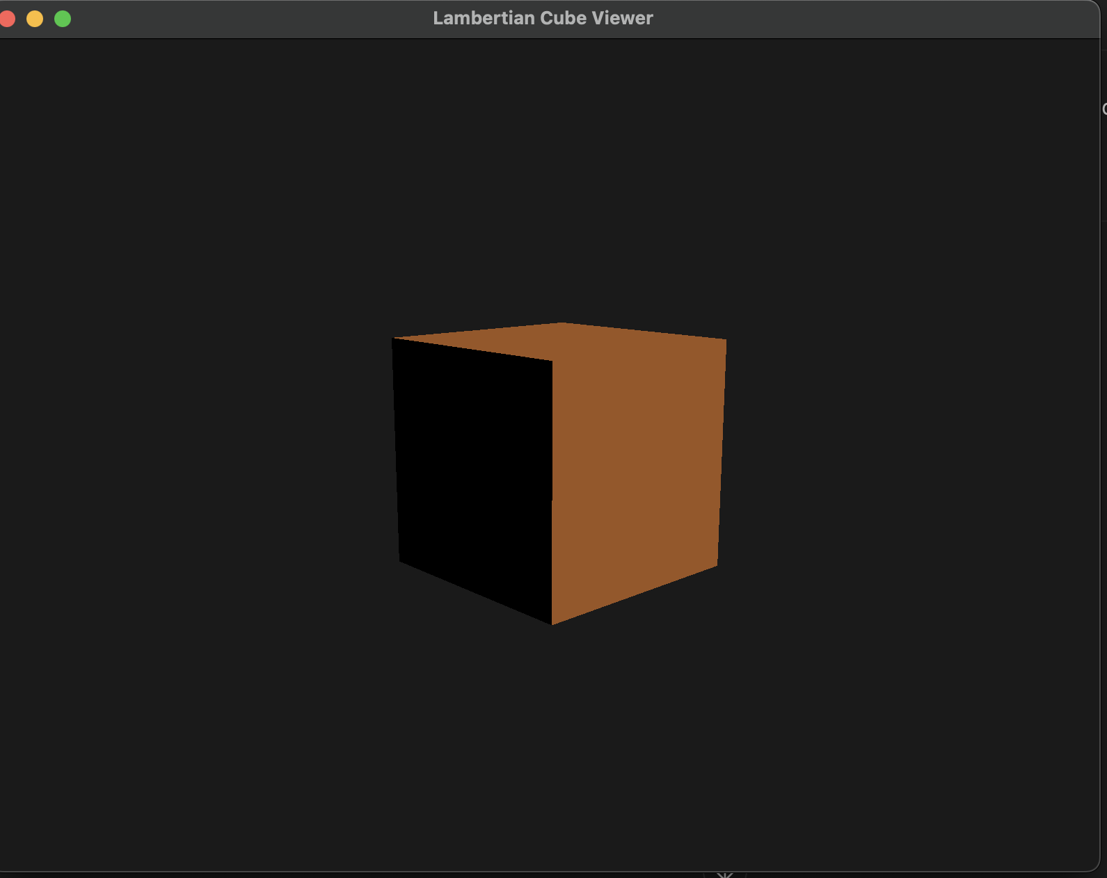
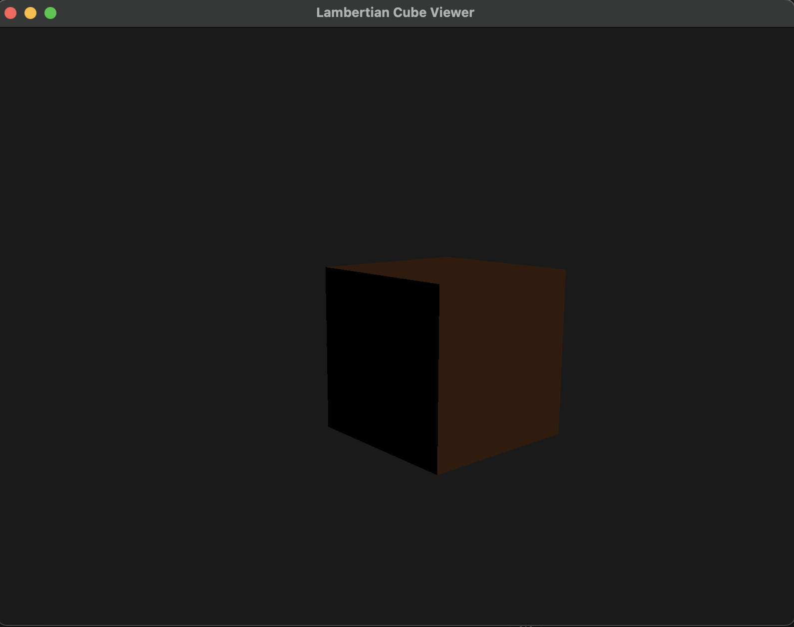
To visualize the effect of Lambertian model.
What I Built
Controls
Use WASD keys to move the camera. Mouse movement controls the camera’s yaw and pitch, allowing free-look navigation. Use 1 and 2 to toggle between [1] simplified lambertian and [2] Use ESC to leave the program.
Shader Logic
Vertex Shader
-
gl_Positiondefines the vertex position in clip space, and is used by the GPU’s fixed-function pipeline to perform viewport transformation and rasterization. It is computed via the standard MVP (Model–View–Projection) matrix pipeline. -
Normalis transformed using the inverse transpose of the model matrix (transpose(inverse(model))). This is required because applying the model matrix directly to normals can distort them, especially under non-uniform scaling or skewing, which breaks the perpendicularity between surface normals and surfaces. The inverse-transpose corrects this distortion and ensures accurate lighting calculations. -
FragPosstores the vertex position in world space. Although the current shading model (Lambertian) doesn’t rely on position, passingFragPosto the fragment shader lays the groundwork for more advanced effects (e.g., point lights, attenuation, or specular highlights) that do.
Note: If a variable passed from the vertex shader to the fragment shader is never used in the fragment shader, modern GLSL compilers may optimize it out during compilation.
Fragment Shader
-
The fragment shader uses the interpolated surface normal (from the vertex shader) and a light direction provided as a uniform from the CPU.
-
Lighting is computed using the Lambertian reflectance model, where the diffuse component is calculated as:
diffuse = max(dot(n, l), 0.0)Here,nis the normalized surface normal, andlis the normalized direction to the light source. This results in a cosine falloff, producing smooth, realistic shading based on the angle between the light and the surface. -
The diffuse reflectance coefficient
Kdis currently hardcoded in the shader as a constant RGB value. In a full material system, this would typically be supplied via a uniform or sampled from a texture.
Screenshots
Key Learnings
1. How Lambertian BRDF Connects with Lighting Models
At first glance, the Lambertian BRDF seems deceptively simple:
$f_r = \frac{\rho}{\pi}$
This states that the surface reflects light equally in all directions (perfectly diffuse), and $\rho$ is the surface albedo (reflectance color).
But to compute the actual outgoing radiance $L_o$ observed from the camera, we use:
$L_o = f_r \cdot L_i \cdot \cos \theta_i$
- $L_i$: incoming radiance from the light source (not a direction)
- $\cos \theta_i = \max(0, \mathbf{n} \cdot \mathbf{l})$: angle between surface normal and light direction
So how does a lighting model like a point light provide $L_i$?
Point Light Example:
Let:
lightPos= light source position in world spacelightColor= base intensity or radiant flux at reference distanceFragPos= world-space position of shaded point
In the shader:
vec3 L = normalize(lightPos - FragPos);              // Direction to light (\omega_i)
float distance = length(lightPos - FragPos);
float attenuation = 1.0 / (distance * distance);     // Inverse-square law
vec3 Li = lightColor * attenuation;                  // Incoming radiance approximation
Now apply Lambert:
float NdotL = max(dot(Normal, L), 0.0);
vec3 Lo = (albedo / PI) * Li * NdotL;
So:
- The BRDF stays the same: $f_r = \rho / \pi$
- The lighting model gives you $L_i$ based on light position, distance, and falloff
- The final shaded result $L_o$ combines the BRDF, light direction, and intensity
This is why lighting models and BRDFs are separable: BRDF says “how light is reflected” and the lighting model says “how much light arrives.”
2. What Does RTR4 Mean by “Ray Density”?
RTR4 Chapter 5.2 uses “ray density” as an intuitive geometric explanation for why light intensity decreases with distance from a point source.
“The spacing between light rays increases with distance, so the density of rays hitting a surface falls off as $1 / r^2$.”
This leads us to:
$\text{Irradiance} \propto \frac{1}{r^2}$
Let’s define the terms more formally:
Light Intensity (Radiant Intensity, $I$)
- Units: Watts per steradian (W/sr)
- Describes how much power a light emits per unit solid angle
- Property of the light source, not the surface
Radiance ($L$)
- Units: W / (m^2 \cdot sr)
- Describes how much light arrives at or leaves a surface per unit projected area per unit solid angle
- Used as $L_i$ and $L_o$ in BRDFs
Irradiance ($E$)
- Units: W / m^2
- Total incoming light power per unit area (integrates radiance over hemisphere)
Ray Density
- An intuitive stand-in for irradiance or radiance falloff
- Not a strict physical quantity
- Used to explain visually why $L_i$ decreases with distance
So when RTR4 says:
“… ray density is proportional to $1 / r^2$ … and thus the light color $c_{light}$ must be attenuated”
It means:
- We simulate light spreading over space by scaling $L_i$ by $1 / r^2$
- This gives correct behavior for point lights in physically-based shading
3. Deep Dive Clarifications
Why Multiply BRDF by $L_i \cdot \cos\theta$?
The rendering equation integrates incoming light from all directions:
$L_o(\omega_o) = \int_{\Omega} f_r(\omega_i, \omega_o) \cdot L_i(\omega_i) \cdot \cos\theta_i \, d\omega_i$
In real-time rendering, we approximate this by evaluating the integrand once using the primary light source:
$L_o \approx f_r \cdot L_i \cdot \cos\theta_i$
- $f_r$ models how the surface reflects light
- $L_i$ is the incoming light’s radiance from a specific direction
- $\cos\theta_i$ represents the projection of light onto the surface normal (i.e., the effective light contribution) — the more oblique the angle, the less energy per unit area
This cosine term comes from geometry: it captures how much of the incoming light “projects” onto the surface area when integrating over a hemisphere.
Why is lightColor / (distance * distance) used for $L_i$?
We treat lightColor as the radiant intensity $I$:
- Radiant intensity = power per steradian (W/sr)
- When light travels a distance $r$, its energy spreads over a sphere of area $4\pi r^2$
Thus, the light reaching a point falls off as:
$L_i = \frac{I}{r^2}$
This is why we compute:
float attenuation = 1.0 / (distance * distance);
vec3 Li = lightColor * attenuation;
It captures the inverse-square falloff seen in natural point lights.
Summary of Radiometric Terms
| Term | Units | Description |
|---|---|---|
| Radiant Intensity | W / sr | Power emitted per solid angle (light source) |
| Radiance | W / (m^2 \cdot sr) | Power per surface area and direction ($L_i$) |
| Irradiance | W / m^2 | Total incoming light per area |
Next Week
Let’s import a real asset. Stay tuned!